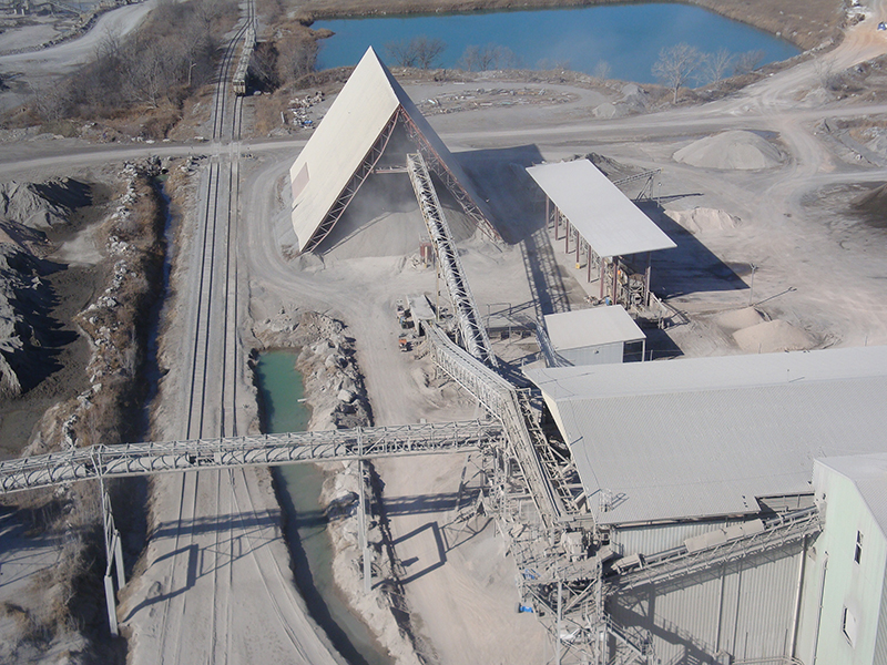
Rulmeca Corporation has supplied thousands of Motorized Pulleys to drive conveyors in a “dual drive” configuration. This aerial photo shows a tunnel reclaim belt conveyor after it was converted from a single (head) drive to a dual (head and tail) drive configuration more than nine years ago. Prior to the conversion, the convex reclaim conveyor belt would “bounce” up, as much as four feet, off the troughing idlers when starting up in an empty condition. This blog post explains how re-orienting conveyor belt tensions by means of dual drive technology can yield a significant beneficial result.
ABOUT RULMECA CORPORATION
We supply Motorized Pulley belt conveyor drives, serving equipment manufacturers directly and end users through a network of independent distributors & local service providers throughout the United States and Latin America.
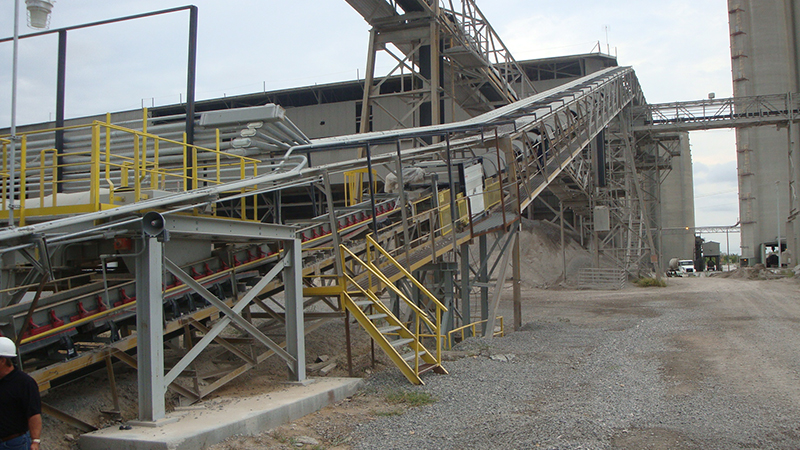
This photo shows a side view of the convex segment of the reclaim conveyor belt (at exit of tunnel). Note that material is carried on a 30 inch wide belt, supported on 35 degree troughing idlers, and elevated 138 feet above the tunnel floor to a transfer tower on the 550 foot long conveyor. Initial conversion from one 75 HP exposed conveyor drive at the head position to two Motorized Pulleys, each at 50 HP, in the head and tail positions was made to provide more drive power to the system. However, separating the drives resulted in redistribution of belt tension, as described below.
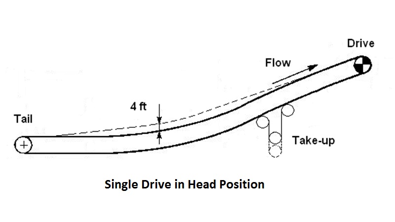
This diagram shows the area of maximum belt bounce, near the tunnel exit, caused by relatively high “effective tension” during start-up with an empty belt. Although the belt tension required to start an empty belt is smaller than for a full belt, “chain theory” states that an empty belt catenary will be very flat (for a given belt tension) because the radius of the catenary is inversely proportional to the weight of the belt (i.e. chain).
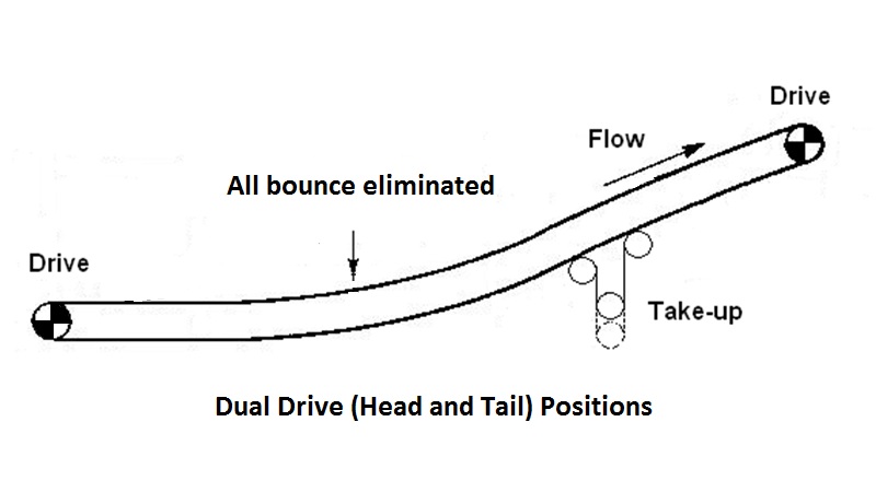
When simultaneously starting both motors in a head and tail drive system, as shown above, the tail drive “feeds” belt onto the carrying strand, reducing the tension between the tail drive and the convex section of belt. The tail drive also provides all of the tension required to overcome friction and momentum of all non-driven pulleys, all return idlers, and all of the return strand of belt. This reduces the required effective tension at the head pulley.
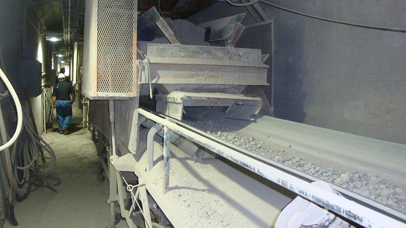
This photo shows one of five tunnel feeders which were susceptible to damage during empty belt start-up prior to the elimination of belt bounce. Sometimes belt bounce would damage the belt and sometimes belt bounce would damage the feeder or feeder structure.
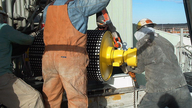
Installation of both Rulmeca Motorized Pulleys was accomplished in one shift. As shown here, the drives are compact, only 24 inches in diameter. Each 75 HP model 630H internally-powered drive pulley weighs only 1,850 lbs and is fastened to the conveyor structure with four bolts.
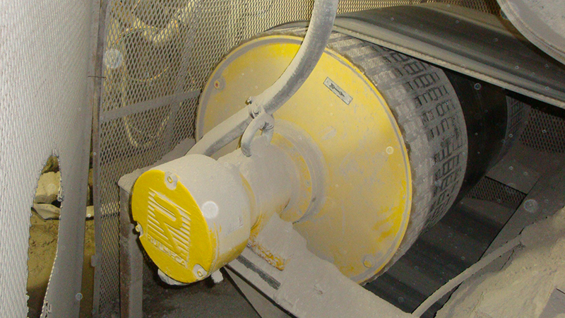
Prior to the installation of a Motorized Pulley in the tail drive position within the tunnel, as shown in this photo, plant personnel expressed concern about possible damage to the drive because a high water table periodically floods the tunnel. However, each drive is protected by its IP67 seal system. Tunnel flooding has not damaged the drive during more than nine years of operation.
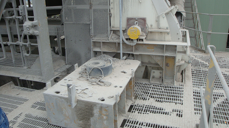
Photo shows “footprint” of original exposed drive system. Note that the Motorized Pulley contains its motor and gearbox within the pulley shell. Therefore, the large base required for the original exposed motor and gearbox is no longer needed.
