
We supply Motorized Pulley belt conveyor drives, serving equipment manufacturers directly and end users through a network of independent distributors & local service providers throughout the United States and Latin America.
HOW THERMAL AND OVERCURRENT PROTECTION WORK
This video explains how thermal and overcurrent protection works, with emphasis on preventing damage to three-phase motors, which power Motorized Pulley conveyor belt drives. Use this video in conjunction with our growing library of tutorials on how to design and maintain bulk handling belt conveyors.
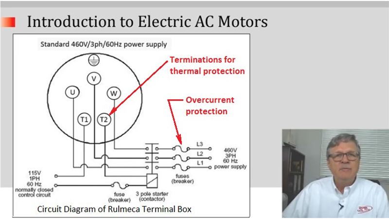
This circuit diagram shows how three-phase AC electric power is connected to the Rulmeca Motorized Pulley with phase one connecting to terminal U, phase two connecting to terminal V, and phase three connecting to terminal W.
This symbol shows that this three phase power supply is protected from drawing too much current by an overcurrent protection device (i.e. fuses or a breaker). Note also, that the standard Rulmeca thermal protection switches, which are built into the Motorized Pulley stator winding, must be connected to a normally-closed control circuit, which can cut power, if required. The termination points are labelled T1 and T2.
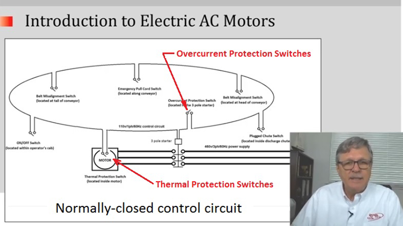
This circuit diagram illustrates a normally-closed controlled circuit in a typical conveyor belt. Note that the diagram shows an on/off switch. It also shows, from left to right, a belt misalignment switch, an emergency pull cord switch, another belt misalignment switch, a plugged chute switch, and so forth around the closed loop. Note how the thermal protection switches (inside the motor) are connected into the normally-closed control circuit. This control circuit is connected to the three-pole starter, which can cut power, if necessary.
We hope you enjoyed this tutorial. For more informative tutorials please subscribe to our YouTube channel. Thank you very much.