
We supply Motorized Pulley belt conveyor drives, serving equipment manufacturers directly and end users through a network of independent distributors & local service providers throughout the United States and Latin America.
HOW TO CALCULATE HOPPER DRAG LOAD AND REQUIRED POWER. HOW TO DESIGN HOPPER FEEDER CONVEYOR PRESSURE RELIEF (PART 2 of 2)
This video explains how to calculate hopper drag load on feeder conveyors and how to reduce that load through the installation of hopper pressure relief systems. It also explains how to convert hopper drag load into required conveyor drive power. It is the second of a two-part tutorial on designing hopper feeder conveyors. Use this video in conjunction with our growing library of tutorials on how to design and maintain bulk handling belt conveyors.
This lesson presents arching theory, how to calculate hopper drag load, how to design hopper pressure relief, and how to calculate the power required to overcome hopper feeder drag. In our first tutorial, we presented the purposes of hoppers, standard conveyor belt loads, and special hopper loading.
![]()
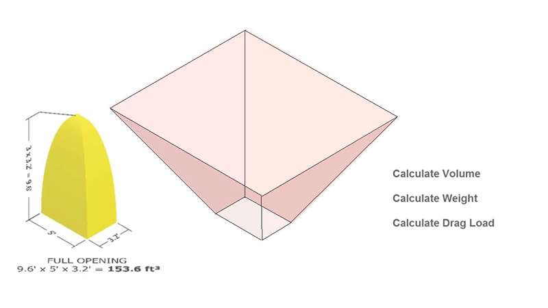
How do we calculate the drag force which a hopper exerts on a conveyor belt? The secret is that we do not need to consider the complete weight of material in the hopper, but only the amount of material which is considered “active”, as shown beneath this parabolic shape.
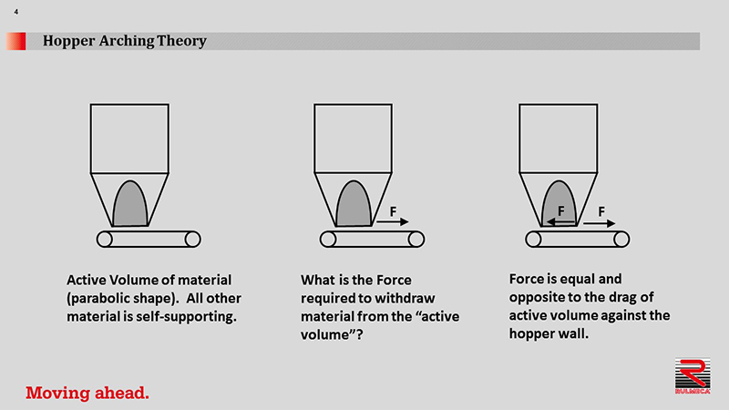
To determine hopper drag load, simply calculate the weight of “active material” and apply a cutting force factor. The active zone is defined by the length and width of the hopper opening, called L and W.
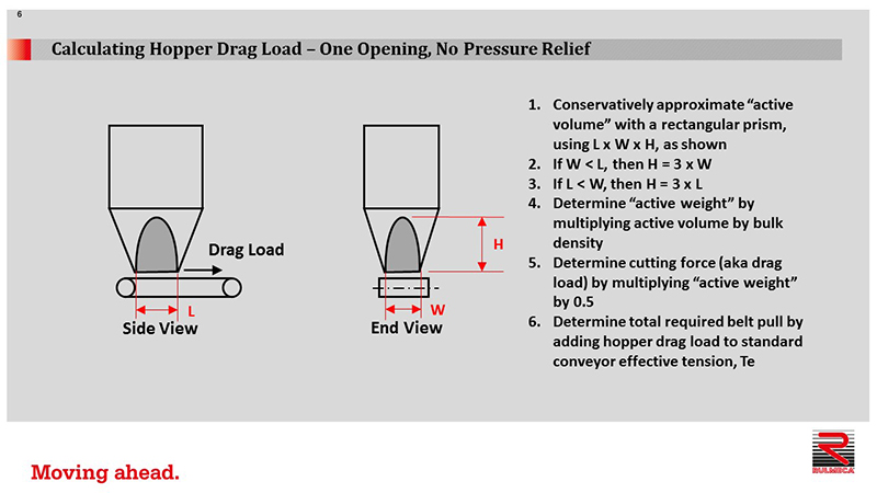
We can conservatively approximate the active volume with a rectangular prism, rather than a parabolic shape.
Active volume = L x W x H
If the width is smaller than the length, assume height = 3 x W. If the length is smaller than the width, assume height = 3 x L.
We can now determine the active weight as follows.
Active Weight = volume x bulk density
We can then determine the drag load (aka “cutting force”) as follows.
Drag Load = Active Weight x 0.5
Now we can determine the total required belt pull by adding hopper drag load to the standard conveyor effective tension (Te).
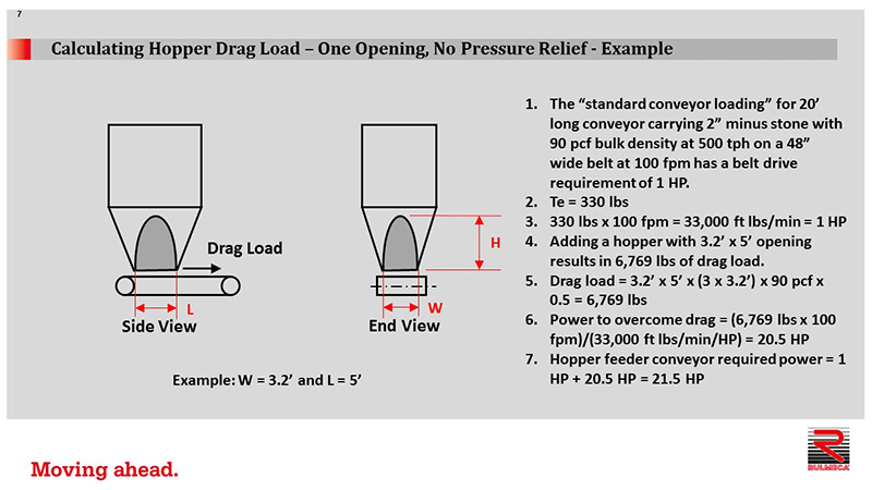
In this example, we have one opening and no pressure relief at the hopper bottom. The standard conveyor loading for a 20 ft long conveyor carrying 2” minus stone with a 90 pound per cubic foot (pcf) bulk density at 500 tons per hour (tph) on a 48 in wide conveyor belt at 100 ft per minute (fpm), has a belt drive requirement of 1 HP. Effective tension (Te) = 330 lbs.
Required power = 330 lbs x 100 fpm= 33,000 ft-lbs/min
1 HP = 33,000 ft-lbs/min
Adding a hopper with an opening 38” wide and 60” long results in a hopper drag load of 6,769 lbs, as follows.
Active Volume = 3.2 ft x 5 ft x 3(3.2 ft) = 150 ft3
Active Weight = 150 ft3 x 90 pcf = 13,538 lbs
Drag Load = 0.5 x 13,538 lbs = 6,769 lbs
The power to overcome this drag is calculated as follows.
Required power = 6,769 lbs x 100 fpm = 676,900 ft-lbs/min
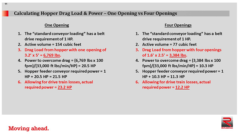
Required power = (676,900 ft-lbs/min)/(33,000 ft-lbs/min per HP) = 20.5 HP
Adding the hopper drag power requirement to the standard conveyor drive requirement of 1 HP yields a raw horsepower requirement of 21.5 HP.
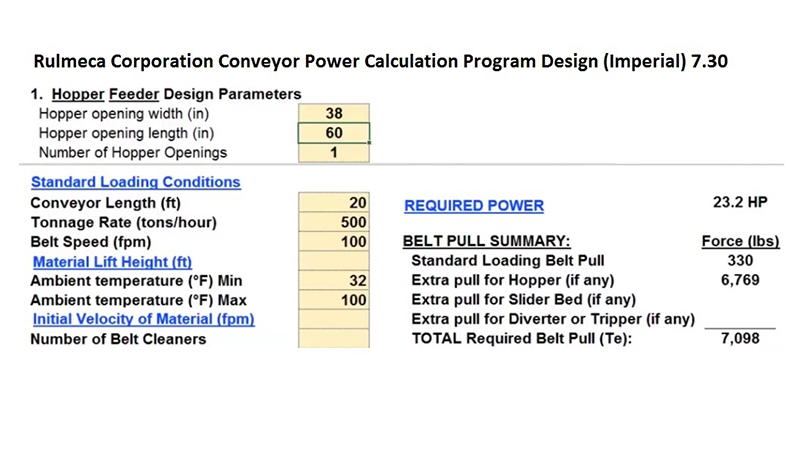
The Rulmeca Corporation Conveyor Drive Power Calculation Program “Design Imperial 7.30” may be used to add hopper drag load to a standard loading condition. As shown below, a conveyor with a length of 20 ft, a handling rate of 500 tph, and a belt speed of 100 fpm has been preloaded, showing that it requires approximately 1 HP to carry the load.
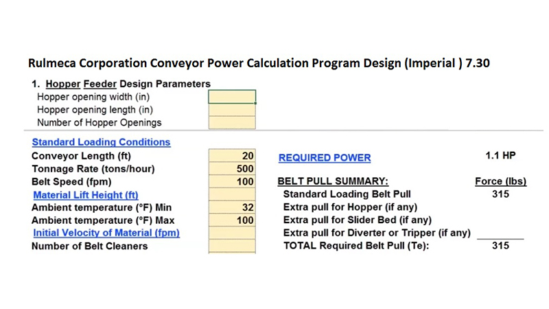
To add a hopper drag load, simply enter the width at 38 in, the length at 60 in and the number of openings of 1 to the program. Note that a hopper drag load of 6,769 lbs has been added, bringing total Te, effective tension, to more than 7,000 lbs. Note that we now have a power requirement of 23.2 HP, including an allowance for gear losses.
How is it possible to relieve pressure from the conveyor belt beneath the hopper opening? It is essential to minimize the hopper opening as much as possible without restricting material flow. We should add pressure relief as close as possible to the bottom of the hopper opening. In this example, we will add one inverted angle to convert one hopper opening to two hopper openings. We’re going to reduce L, length, while keeping W, width, constant.
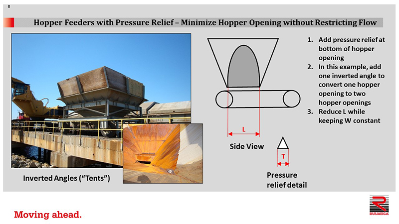
In the photograph, you can see a typical hopper from the side and from the top. Notice that an inverted angle has been welded to the bottom of the hopper opening. These are also called “tents”.
We can approximate two active volumes with two rectangular prisms in which L’ = L – T.
T = width of the inverted angle.
To conservatively simplify the calculation, ignore T.
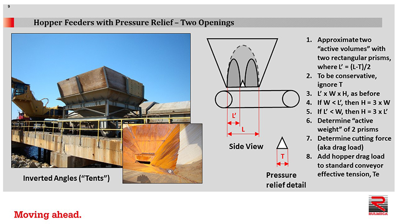
Therefore, each prism’s volume may be calculated as follows
Volume of 1 prism = L’ x W x H
If L’ < W, H = 3 x L’
If L’ > W, H = 3 x W
The active weight of 2 prisms may be calculated as follows
Total active weight = 2 prisms x volume of each prisms x material bulk density
Hopper drag load = 0.5 x total active weight
To determine required hopper feeder drive power, add the hopper drag load to a standard conveyor effective tension, Te.
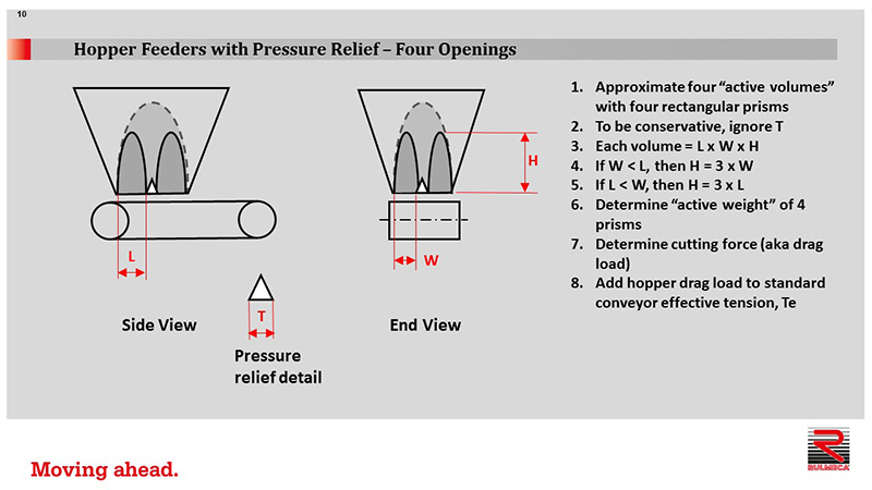
Now let’s review how to decrease hopper pressure even more. If changing one opening to two openings is good, then changing one opening to four openings may be even better. Here’s how to calculate that. Approximate four active volumes with four rectangular prisms using the techniques mentioned previously. Continue to ignore T and calculate the volume of each prism, as before.
To calculate the drag load in this example, calculate the four volumes, determine the active weight of the four prisms, determine the total cutting force by multiplying the total active weight by 0.5. Finally, add hopper drag load to the standard conveyor effective tension, Te, and calculate required power.
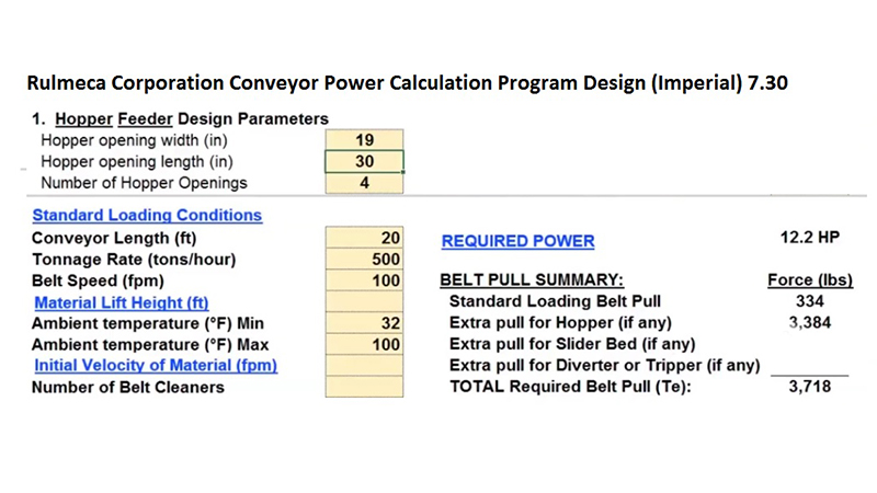
Now let’s use the Rulmeca Corporation program to see the dramatic reduction in required hopper feeder conveyor drive power by adding pressure relief. Modify one hopper opening of 38” x 60” to four hopper openings, each at 19” wide x 30” long. Notice that the required power drops from 23.2 HP to 12.2 HP. Hopper drag was reduced from more 6,769 lbs to 3,384 lbs, yielding a total effective tension, Te, equal to 3,718 lbs.
This tutorial has shown that arching theory may be used to approximate hopper surge loading on feeder belt conveyors. Only the active volume of material in the hopper, rather than the total volume, needs to be considered.
This lesson demonstrated how to calculate hopper drag load by approximating parabolic shapes with rectangular prisms, then calculating their weight and applying a cutting factor.
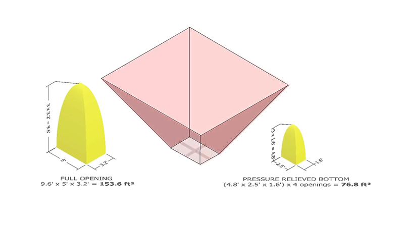
Finally, we presented a technique to calculate how to reduce hopper drag load by adding pressure relief to hopper bottoms. This animation shows that revising a single opening hopper bottom to a four opening hopper bottom cuts the active volume in half.
In summary, the active weight of material on the feeder belt and, therefore, hopper drag load are linearly proportional to the active volume. Our example demonstrated that reducing active volume from 154 ft3 to 77 ft3, reduces drag load from 6,769 lbs to 3,384 lbs. This, in turn, reduced required conveyor drive power from 23.2 HP to 12.2 HP.
For more conveyor drive design tips, or to obtain a copy of our belt conveyor power calculation program, go to RULMECACORP.COM or subscribe to our YouTube channel. Thank you very much.