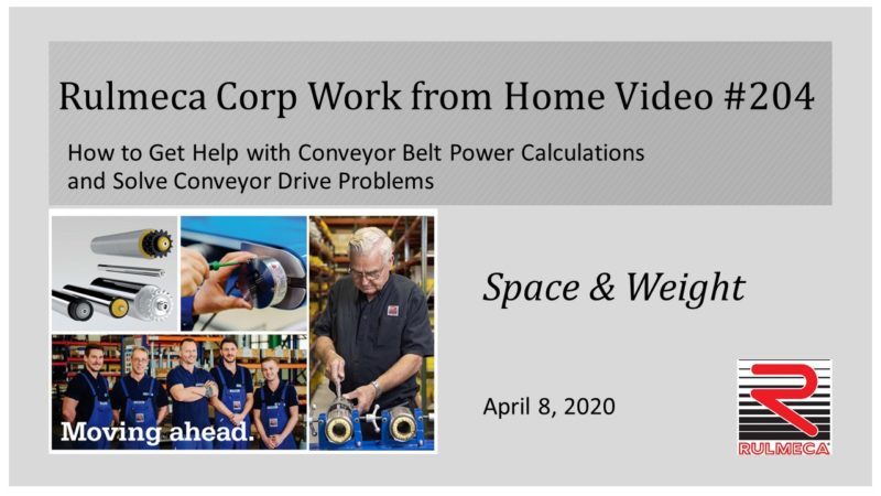
We supply Motorized Pulley belt conveyor drives, serving equipment manufacturers directly and end users through a network of independent distributors & local service providers throughout the United States and Latin America.
HOW TO SOLVE CONVEYOR DRIVE SPACE AND WEIGHT PROBLEMS
This is our 4th video in our “Work from Home” video series. Today’s topic addresses space and weight problem with conveyor drive systems. Our video is sponsored by Rulmeca Corporation and I’m your host, Mike Gawinski.
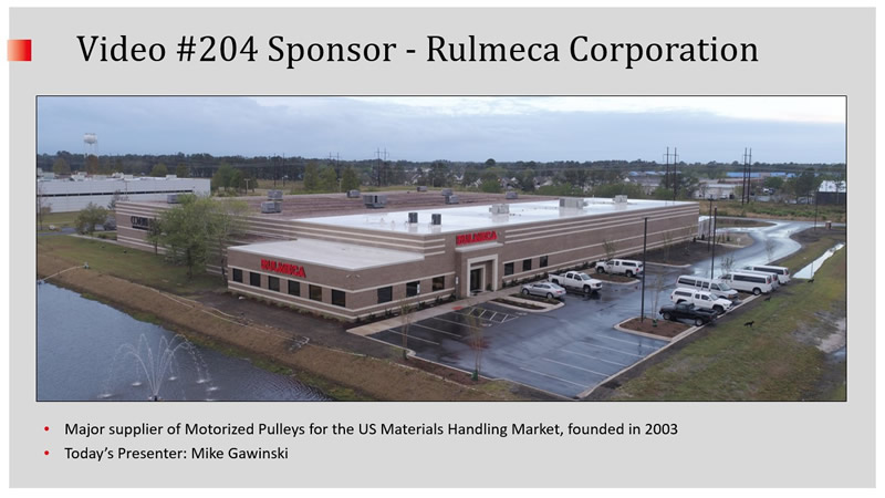
We’re a major supplier of Motorized Pulleys for the US materials handling market.
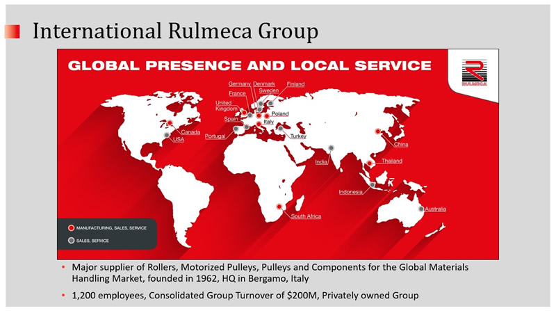
We are part of the International Rulmeca Group, major supplier of rollers, Motorized Pulleys, pulleys and components for the global materials handling market ,headquartered in Bergamo, Italy.
Effective March 30th, Rulmeca Corporation is designated as essential during the virus response. Therefore, we’re continuing to produce and repair Motorized Pulleys. However, all of our sales and administrative staff are working from their homes, as I am today. This video is for anyone interested in belt conveyor operations and design.
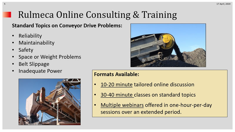
We launched free online consulting and training services in April in three formats:
- 10 to 20 minute tailored online discussions
- 30 to 40 minute classes on standard topics
- 60 minute webinars standard and custom-made
Due to COVID-19 we cancelled all 2020 seminars in Wilmington and replaced them with webinars. Webinars will include lectures and workshops, as needed.
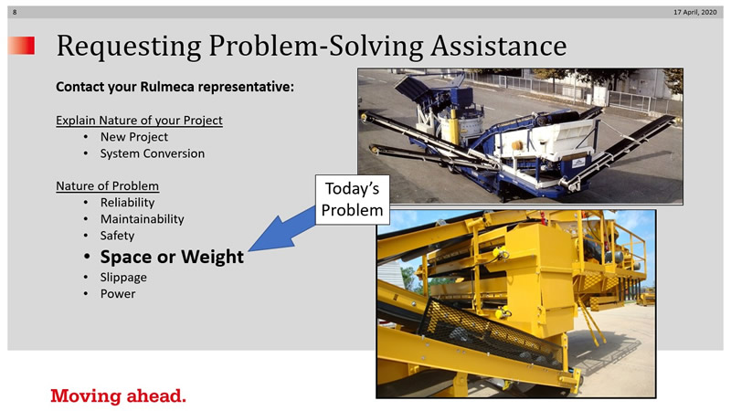
Today’s topic is space or weight problems with conveyor drive systems. It’s important you identify whether your project is:
- new project or
- conversion of an existing system
Whether your plant is portable or fixed will determine how you approach the problem of space and weight. How do we solve these problems?
- Identify the conveyor drive problem
- Request technical assistance
- Consider a technical solution
- Obtain and consider a commercial response
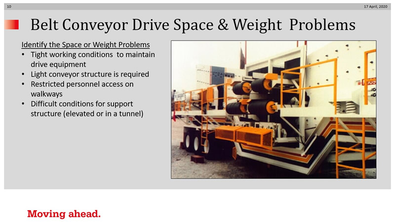
The space and weight problems we’ll address today include tight working conditions, light conveyor structure, restricted personnel access , and difficult conditions for the support structure.
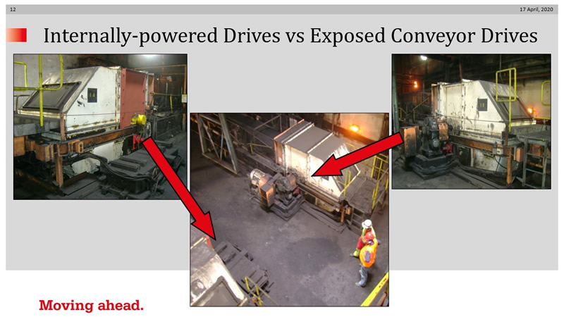
To request technical assistance, download, fill in, and submit an app sheet. Today’s presentation will be contrasting internally powered drives with exposed conveyor drives. This picture shows a pit beneath a power plant coal train dumper with an exposed drive system on the right and an internally powered drive system on the left.
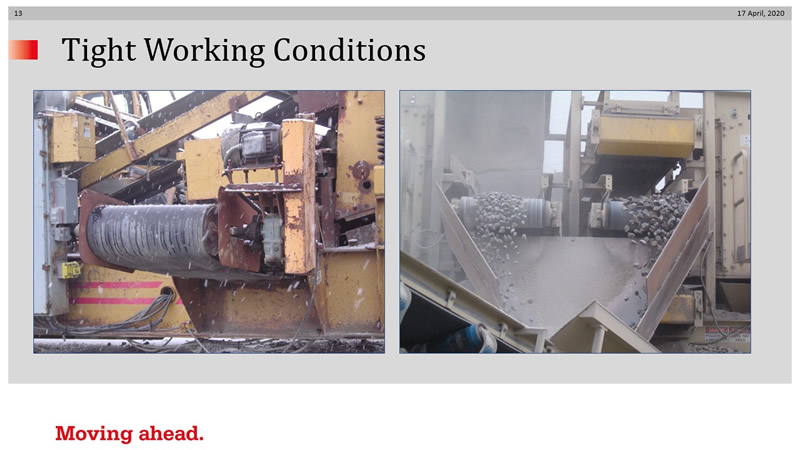
Tight working conditions: The left photo shows an old exposed drive on a cross belt, which is a “knuckle buster “ to maintain because of limited space, especially in a mobile plant. The photo on the right shows cross belts driven by Motorized Pulleys catching cuts from two screens (one on the left and one on the right). As you can see, using an internally-powered drive streamlines the design and simplifies maintenance.
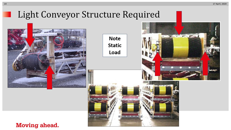
Light Conveyor Structure – Static Load: Note that an exposed drive system always consists of an overhung load. The left photo shows how an exposed drive, cantilevered toward the left of the conveyor, puts most of its dead weight on the left truss. The right photo shows how an internally-powered drive centers the static between the two support trusses. This not only streamlines the design, but also enables the designer to use a lighter structure.
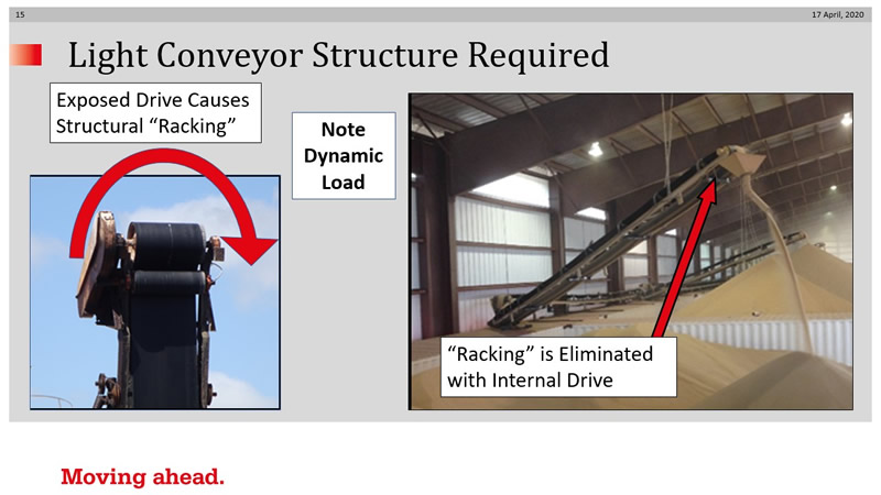
Light Conveyor Structure – Dynamic Load: The left photo shows how an exposed system “racks” or twists the conveyor structure during start-up. The structure needs to be heavy enough to resist that racking action. The right photo shows how, with an internally-powered drive, there is no racking action because of how the torque is transmitted into the conveyor structure. That feature is especially important at this project because this light conveyor is supported by chain from roof rafters.
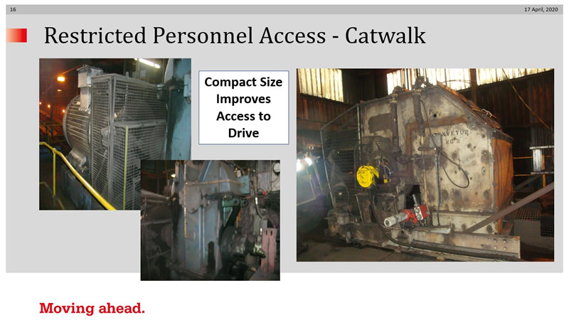
Restricted Personnel Access – Catwalk: The left photos show restricted access at a 150 HP conveyor drive at a power plant. The right photo, taken after conversion to an internally-powered drive, shows the improvement to personnel access. Workers, for example, can easily maintain the belt cleaner without having to squeeze between gearbox, motor, and chute.
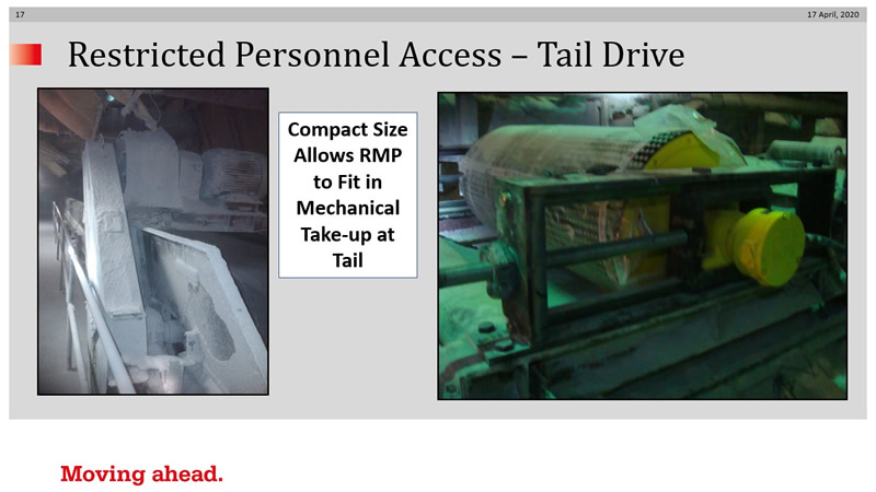
Restricted Personnel Access – Tail Drive: These “before” and “after” photos are from a loading conveyor above a 100-foot-deep hopper in an underground mine. The exposed drive was originally installed at the discharge (head) end, which required maintenance personnel to be suspended above the hopper opening. Converting the system to an internally-powered drive in the tail position in a mechanical take-up enabled maintenance people to access it safely from the catwalks at the side of the hopper.
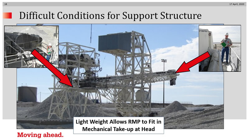
Difficult Support Structure Conditions: When this radial stacker was converted from a single tail drive to a dual drive, the operator was concerned with replacing an idler head pulley with a driven head pulley because of the light weight of the conveyor structure. The 60 HP Motorized Pulley only weighed 2,400 pounds whereas original idler pulley 3,300 pounds.
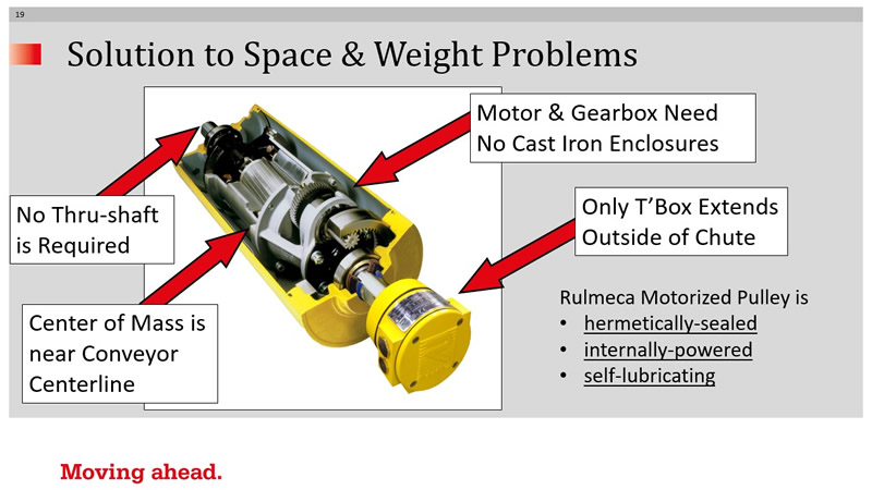
This cutaway photo shows how an internally-powered drive offers compact size and a well-balanced load to the conveyor structure. It also shows why its weight is 30% lighter than an exposed drive..
- No large through-shaft is required because the motor and gearbox frames act like a strong beam. Therefore, only two small lightweight stub shafts are necessary
- Center of mass of the drive train is at the conveyor center line
- No “extra” cast iron enclosures are required for the motor and gearbox because the pulley shell serves as an enclosure
- Only the terminal box extends through the chute wall
If you request technical assistance from us, we will provide power calculations as well as cross section and trajectory plots to ensure the geometry is appropriate for your conveyor. The program is also downloadable from our website for do-it-yourselfers.
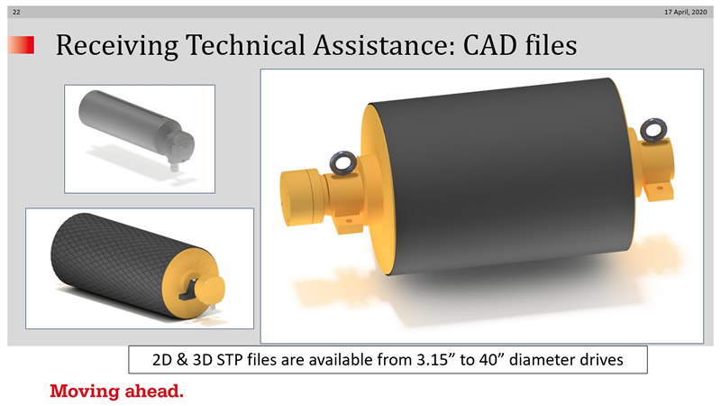
We also have 2D and 3D STP files readily available for all Motorized Pulleys, with diameters from 3.15 to 40 inches, enabling engineers to import them into their conveyor structure files.
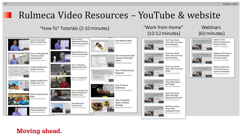
That concludes the topic of space and weight problems. Thank you for watching today. Don’t forget that we now have free online consulting and training service available. Also, remember that we have a growing library of “How to” video tutorials as well as our six “Work from Home” videos, and all webinar recordings on our website and YouTube channel.
To contact us, please send us an email at sales-us@rulmeca.com or call us at (910) 794-9294. Thank you for spending time with us today. We all hope this virus crisis will be over soon. Let’s keep our chins up.
