
We supply Motorized Pulley belt conveyor drives, serving equipment manufacturers directly and end users through a network of independent distributors & local service providers throughout the United States and Latin America.
HOW TO UNDERSTAND HOPPER PURPOSES AND FUNCTIONS (PART 1 of 2)
This video explains the purposes and functions of hoppers and serves as an introduction to the company’s two-part tutorial on how to design hopper feeder conveyors. Use this video in conjunction with our growing library of tutorials on how to design and maintain bulk handling belt conveyors.
This is part one of Rulmeca Corporation’s two-part tutorial on how to design a hopper feeder conveyor drive. This lecture includes three parts: the purposes of hoppers, standard conveyor belt loads, and special hopper loading. A separate video will be present arching theory, calculating hopper drag load, and pressure relief tips.
The four purposes of hoppers are:
- Material storage
- Material blending
- Interface between batch loading and continuous flow
- Material metering
Material Storage
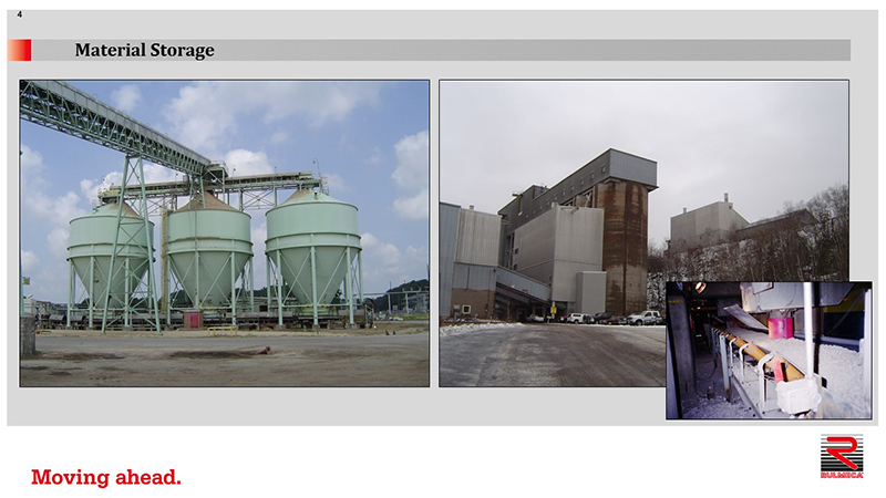
The left picture shows that a pulping plant stores wood chips in three separate bins. Each bin is loaded by a standard belt conveyor. The material is taken away from the hoppers using a drag chain conveyor, moving the chips into the pulping plant for production.
The right picture shows several silos used at an iron ore mine in Minnesota. The silos store the taconite ore and limestone. They are loaded by a standard troughing belt conveyor at the top. Down below you can see a closeup of a typical draw-down point. Material is removed from the silo through the draw-down points and taken away continuously by a troughing belt conveyor.
Material Blending
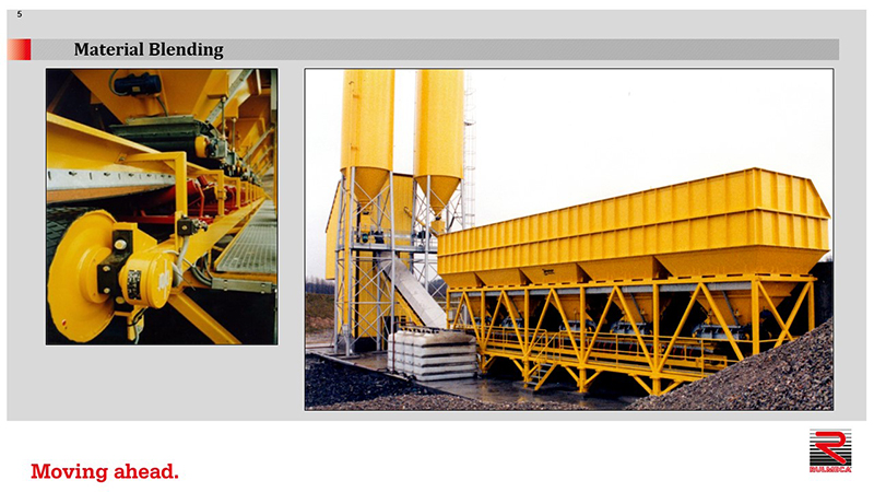
This photo shows hoppers used for material blending. In this five pant-leg configuration each pant-leg contains a different ingredient. For example, large gravel, a smaller size of gravel, sand, and so forth. Each pant-leg has a hopper feeder conveyor at the bottom. Each small hopper feeder conveyor has a drive and the main long collecting conveyor has a drive.
Interface between batch loading and continuous flow
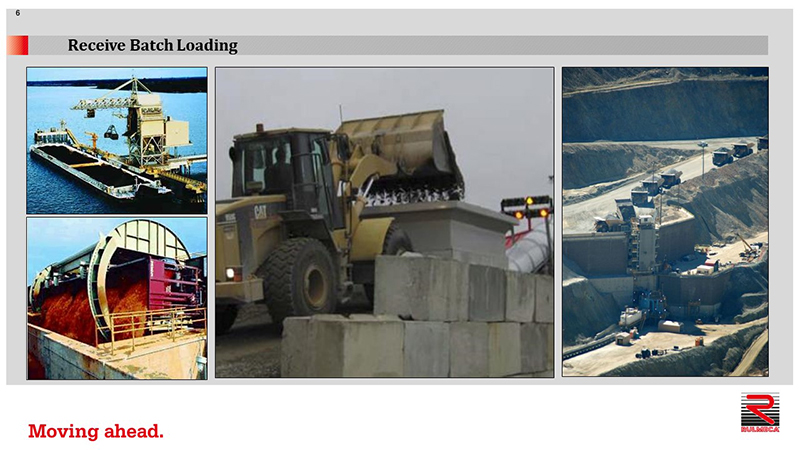
Hoppers may also be used as an interface between batch and continuous material flow. A clamshell ship unloader removes coal in batches, one clamshell load at a time. The material is deposited into the hopper, which accumulates the material and continuously feeds it onto the dock conveyor.
Here is an example of a rotary railcar dumper. Railcars are dumped one at a time and the material is deposited into a hopper. Beneath the hopper is a feeder conveyor removing material continuously.
Here we also see a front-end loader moving stone into a hopper, which then transfers the material continuously onto a belt conveyor. And, finally, we see a variety of mine haul trucks waiting in line to dump their material into this hopper. The feeder conveyor beneath the hopper feeds material continuously to the long takeaway belt.
Material Metering
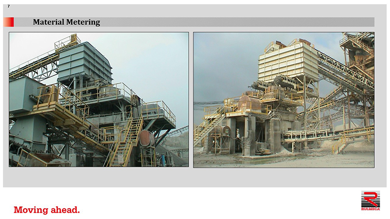
Metering hoppers are designed to supply material onto conveyors at various rates. Speeding up or slowing down feeder conveyors (or increasing or decreasing the size of the feed gate opening) will increase or decrease the rate of material flowing on the feeder conveyor. These two examples show that stone is stored in hoppers and removed with hopper feeder conveyors. Each conveyor is driven by a VFD, which is connected to an ultrasonic probe. Each probe “looks” into the throat of a gyratory crusher giving a continuous signal to its VFD. Each VFD either speeds up or slows down its feeder conveyor to insure the throat of the gyratory crusher is “choke fed”.
Continuous Flow
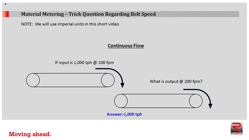
If a conveyor with a belt speed of 100 feet per minute (fpm) transfers 1,000 tons per hour (tph) to another conveyor, which has a belt speed of 200 fpm, what is the rate of output from the second conveyor? The answer is 1,000 tph because the flow is continuous. A different belt speed simply means that the material cross section in the trough of the faster conveyor will be smaller than the slow conveyor. When material flows continuously belt speed does not affect the carrying rate.
Metering Hopper
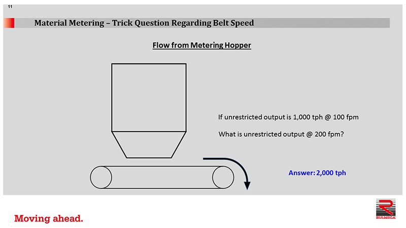
Assume the amount of material in the hopper is unlimited and the output is unrestricted. If the hopper feeder conveyor moves material at 1,000 tph at a belt speed of 100 fpm it will move material at 2,000 tph at a belt speed of 200 fpm. That is because the handling rate is linearly proportional to the belt speed.
The Conveyor Equipment Manufacturers Association (CEMA) conveyor design manual explains how to calculate standard bulk conveyor belt loads in a continuous material flow situation. Notice that material continuously flows through the feed chute onto the conveyor and through the discharge chute off of the conveyor.
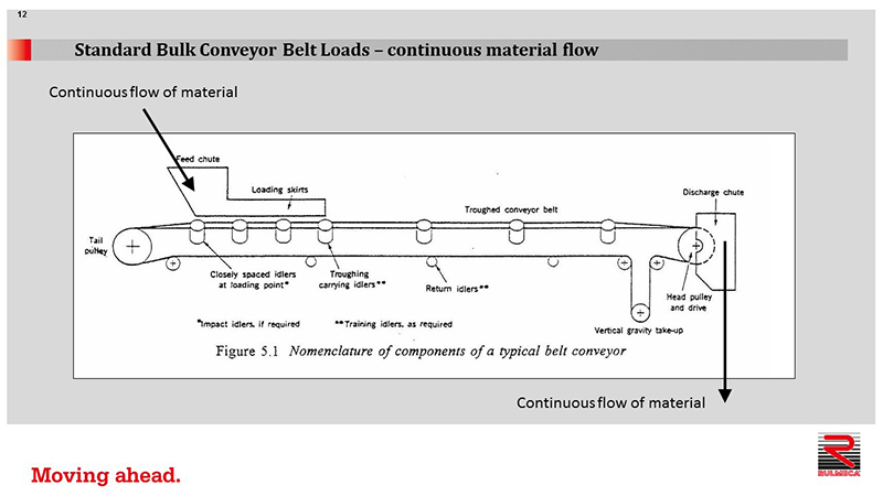
The drawing highlights key features of a typical conveyor belt: drive pulley, troughing idlers, loading skirts, feed chute, tail pulley, return idlers, and gravity take-up with two snub pulleys. The drawing does now show other items such as belt cleaners and slider beds.
Te, effective belt tension, is essential to know to calculate the power required to drive the conveyor belt. Examples of some of the components of Te are listed below.
Tam, for example, is the belt tension required to continuously accelerate material as it is fed onto the belt. In other words, the force required to overcome momentum.
Tb is the tension required to lift or lower the belt.
Tm is the tension required to lift or lower the conveyed material. Tb and Tm are the forces required to overcome gravity.
Examples of some of the components of Te required to overcome frictional drag are: Tbc, which is the tension required to overcome belt cleaner drag; Tsb, the tension required to overcome skirtboard drag; Tx, the tension required to overcome carrying and return idler bearing and seal drag; and Tp, which is the tension required to overcome the resistance of pulleys to rotate on their bearings plus the resistance of the belt to flexure around those pulleys.
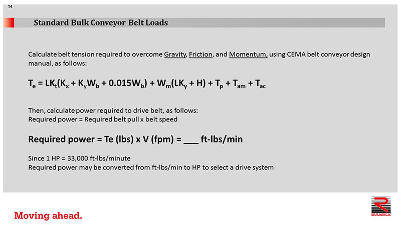
The equation we see here is beyond the scope of this short presentation, but it’s taken from the CEMA belt conveyor design manual, and it shows us how we to calculate the belt tension required to overcome:
- Gravity
- Friction
- Momentum
Once we know the effective belt tension, Te, we can calculate the power required to drive the belt. Required power equals the required belt pull times the belt speed.
Required power = Te x V
Since Te is expressed in pounds and V, belt speed, is expressed in fpm, the product equals a certain number of foot-pounds per minute.
Since 1 HP = 33,000 ft-lbs/min, the required power can be converted from ft-lbs/min to HP, and then a drive system can be selected.
Now let’s examine “special hopper loading” on a feeder belt conveyor. As mentioned previously, we have a certain amount of material in the hopper, which exerts a vertical force on the conveyor beneath it. This “additional vertical force” on the feeder conveyor results in an extra horizontal force against the sidewall of the hopper.
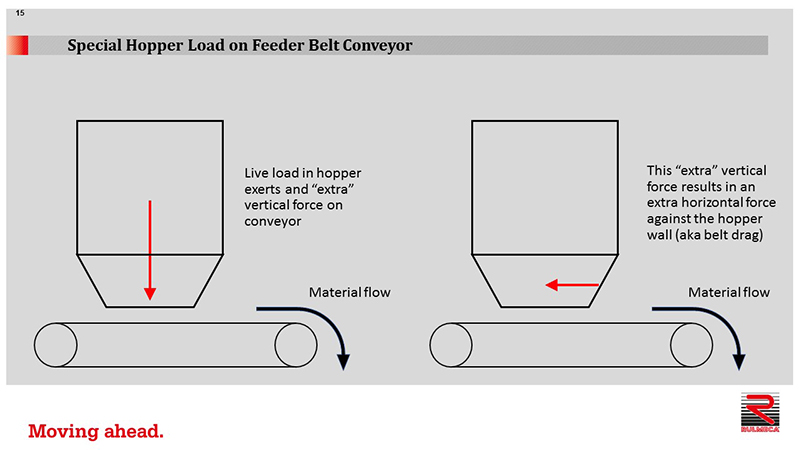
This “extra horizontal force” is another component of belt drag, as illustrated here, and must be added to the effective belt tension, Te, for the conveyor to calculate total required hopper feeder conveyor power.
In part two, we’ll discuss arching theory, calculating hopper drag load, and pressure relief tips. I hope you’ve enjoyed this short tutorial. For more conveyor drive design tips, go to RULMECACORP.COM or subscribe to our YouTube channel. Thank you very much.