
We supply Motorized Pulley belt conveyor drives, serving equipment manufacturers directly and end users through a network of independent distributors & local service providers throughout the United States and Latin America.
HOW TO USE A MULTIMETER (PART 5 OF 6)
This video explains how to use a multimeter to troubleshoot electric motors. It follows our “how to read circuit diagrams” tutorial and is a key part of the company’s six-part tutorial on how to troubleshoot Rulmeca Motorized Pulleys. Use this video in conjunction with our growing library of tutorials on how to design and maintain bulk handling belt conveyors.
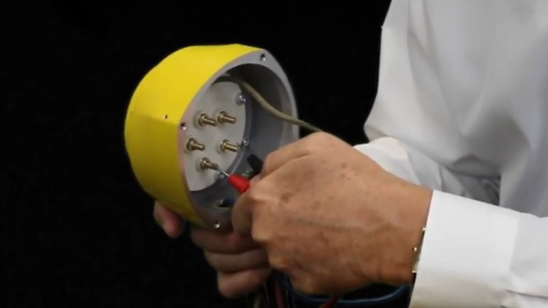
Now that we’ve shown how to use a multimeter, let’s look specifically at a Rulmeca Motorized Pulley terminal box. This box has been disconnected from the Motorized Pulley for demonstration purposes and is not connected to an electrical power source.

First, we must unscrew the four fasteners on the cover, using an Allen wrench, and remove the cover.

Now we can look more closely at the configuration of the Motorized Pulley terminal board. Notice that the three phases of power are connected as follows: phase one is connected to terminal U, phase two is connected to terminal V, and phase three is connected to terminal W. These leads are colored black, white, and red in this example.
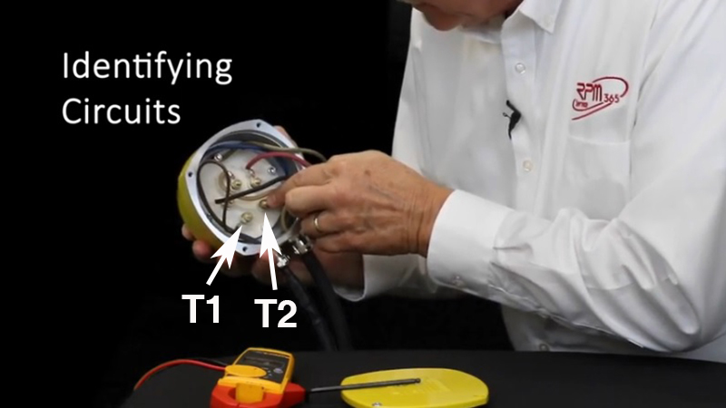
Also notice that terminals T1 and T2 (which are internally connected to three thermal protection switches, wired in series) must be connected to a normally-closed control circuit. In this example, the leads are colored brown and blue.
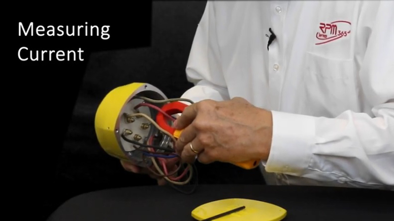
How do we measure the current flowing to the motor? We use a clamp-on Multimeter. We set it to position A, to measure amps, and simply put the clamp meter around each conductor, as shown, one phase at a time.
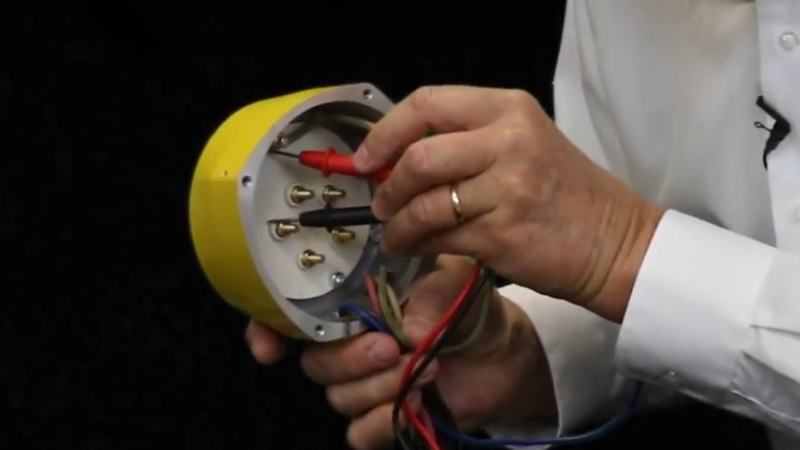
Here is how to measure the resistance in each of the three motor phases. Here, also, is how to measure the resistance across the three internal bimetallic thermal protection switches.
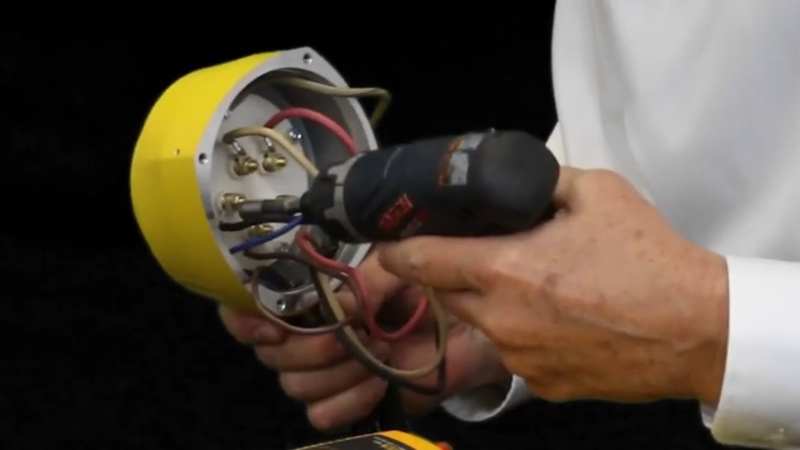
First, disconnect the conductors from each terminal after shutting off the power supply, using an electric screwdriver. We recommend an electric screwdriver to minimize the torque.
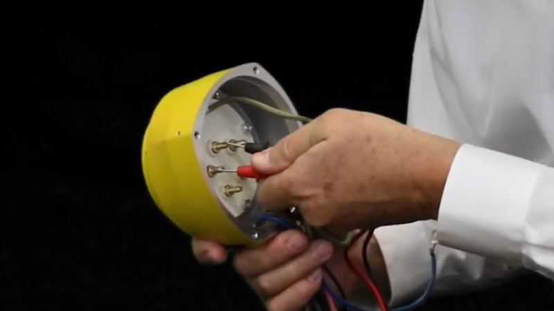
After disconnecting the conductors, measure the resistance as follows. Set the probes between U and V to check the resistance in phase one, V and W to check the resistance in phase two, and U and W to check the resistance in phase three.
To check the resistance across the thermal protection switches, put the probes across terminals T1 and T2.
To check the resistance between each phase and ground, put the probes as follows: between U and the ground lug, V and the ground lug, W and the ground lug.
To check the resistance to ground between the thermal protection switches and ground, put the probes between T1 or T2 and the ground probe.
We hope you enjoyed this tutorial. For more informative tutorials, please subscribe to our YouTube channel. Thank you very much.