
We supply Motorized Pulley belt conveyor drives, serving equipment manufacturers directly and end users through a network of independent distributors & local service providers throughout the United States and Latin America.
HOW TO READ CIRCUIT DIAGRAMS (PART 4 OF 6)
This video explains how to read circuit diagrams and serves as a preface to our “how to use a multimeter” tutorial. It is a key part of the company’s six-part tutorial on how to troubleshoot Rulmeca Motorized Pulleys. Use this video in conjunction with our growing library of tutorials on how to design and maintain bulk handling belt conveyors.
Electrical troubleshooting should always be done by a trained professional, using personal protective equipment. The following troubleshooting tips assume that the conveyor control system has already been checked for “trips”. A conveyor with a normally-closed control system is considered “tripped” when any one of a number of switches is opened. These switches may include: E-stop safety switch, belt misalignment, chute tilt, zero speed, and pull cord safety switches. If the control system is not tripped, we can use a multimeter to perform a variety of checks to diagnose a motor problem, as described below.

Next we will review typical conveyor drive electric motor power and control circuit diagrams as a preface to how to use a Multimeter to measure supply voltage, measure motor current draw, measure motor winding resistance, measure thermal protection switch resistance, and measure motor insulation continuity.

Connect the voltmeter leads between the pulley motor terminals U and V, V and W, and U and W. The three voltage measurements should be balanced, and should not have more than a 5% deviation from the lowest to the highest. The three voltage measurements should also be within 5% of the voltage rating shown on the pulley data plate. This will determine if the supply voltage is getting to the pulley motor terminal board, is the correct amount (for example, if the dataplate says 460 volt, you must verify that you have 460 volts), and is balanced.
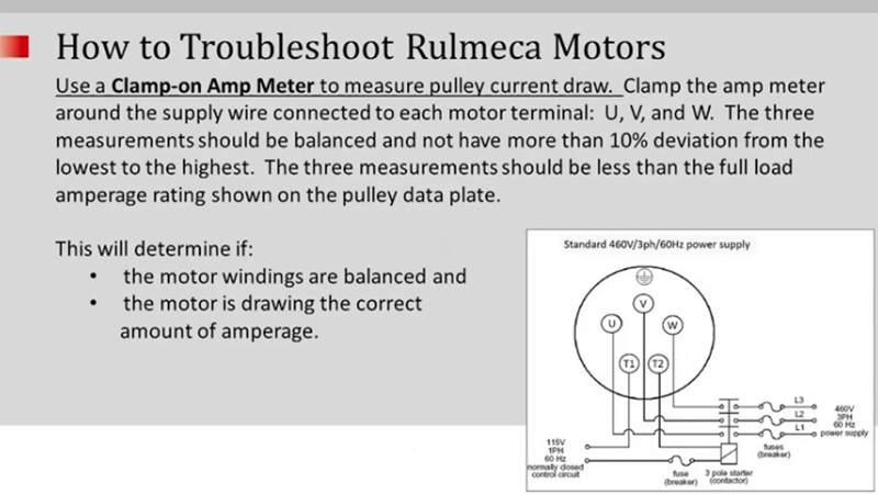
Next you can use the Multimeter clamp-on ammeter feature to measure the pulley drive motor current draw. The clamp meter should be clamped around the power supply wire connected to each motor terminal. For example, the lead connected to terminal U will check phase one, the lead connected to terminal V will check phase two, and the lead connected to W will check phase three. The three measurements should be balanced and should not have more than a 10% deviation from the lowest to the highest. The three current measurements should be less than the specified full load amps (FLA) shown on the pulley motor data plate. These measurements will determine whether or not the motor windings are balanced and the motor is drawing the correct amount of current.
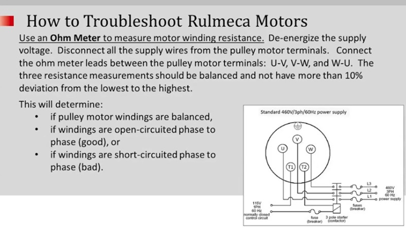
Next, use the Multimeter to measure the motor winding resistance. Of course, you must de-energize the supply voltage, disconnect all supply wires from the pulley motor terminals, and then connect the Ohmmeter leads between the pulley motor terminals as follows: U to V, then V to W, then U to W. The three resistance measurements should be balanced, and should not have more than a 10% deviation from the lowest to the highest. This will determine if the pulley motor windings are balanced and “open-circuited” phase to phase, which is good. Or, if the windings are “short-circuited” phase to phase, which of course is bad.

Next use the Ohmmeter to measure the thermal switch resistance. De-energize the supply voltage, disconnect all the supply wires from the pulley motor terminals, and then connect the Ohmmeter leads to terminals T1 and T2. Look for near-zero resistance (i.e. full continuity). Then, connect the Ohmmeter leads between T1 and Ground, and T2 and Ground, and look for no continuity (i.e. infinite resistance).
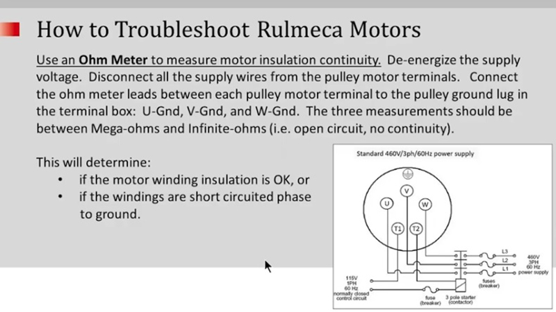
Finally, use the Ohmmeter to measure the motor insulation continuity. De-energize the supply voltage, disconnect all the supply wires from the pulley motor terminals, and then connect the Ohmmeter leads between each pulley motor power terminal to the pulley ground lug in the terminal box. For example, connect U to the ground lug, then connect V to the ground lug, and then connect W to the ground lug. Each of the three measurements should be between megaohms and infinite ohms. In other words the measurements should show an open-circuit (i.e. no continuity). This will verify whether the motor winding insulation is okay or if the windings are short-circuited phase to ground.
We hope you enjoyed this tutorial. For more informative tutorials, please subscribe to our YouTube channel.
Thank you very much.